
Practical skills: Paper 4 Alternative to Practical
Electrical experiments: circuits, meters and resistance
In this note
- AO3Draw circuits with the correct symbols, including variable resistor, thermistor, LDR, diode.
- AO3Connect an ammeter in series and a voltmeter in parallel, and read them.
- AO3Calculate resistance R = V/I and resistance per unit length; investigate wires, lamps, thermistors, LDRs, diodes, series and parallel resistors.
- AO3Give the precautions the scheme rewards (switch off between readings) and find faults in a circuit.
The skills used here: reading meters, tables and s.f., graphs.
Rules to learn
Circuit symbols
A circuit diagram mark needs every symbol right. These are the ones that come up:
| cell (long line +) | |
| switch (open) | |
| lamp | |
| fixed resistor | |
| variable resistor | |
| thermistor | |
| light-dependent resistor | |
| diode | |
| light-emitting diode | |
| ammeter | |
| voltmeter |
Connecting and reading meters
General methodHow to draw any test circuit
- Draw the supply, switch, ammeter and the component in ONE loop (series).
- Add a variable resistor in the loop if the current must be changed.
- Draw the voltmeter on its own branch, joined across the two ends of the component (parallel).
- Mark junctions with dots; use a ruler; no gaps in the wires.
Read meters with the method in Measurements and readings: value of one division, count from the label below the needle, half-division. An ammeter that reads off the end of its scale (beyond full-scale deflection) needs a larger range or a smaller current.
Resistance experiments
| Investigation | Change | Measure | What the results show |
|---|---|---|---|
| length of a wire | length l (crocodile clip on a metre rule) | V and I → R | R ∝ l: straight line through the origin |
| diameter of a wire | wires of different diameter (micrometer) | R | thicker wire, smaller R |
| resistors in series / parallel | the combination | V and I → R | series adds; parallel is less than the smallest |
| filament lamp | the current (variable resistor) | V and I | R increases as the current (temperature) increases |
| thermistor (NTC) | temperature of the water bath | R | R decreases as the temperature rises |
| LDR | light reaching it (distance from a lamp, card covering it) | R or V across it | R increases as the light decreases |
| diode | current (resistors in the circuit) | V and I → R | conducts one way; V stays fairly constant; R increases as the current decreases |
Example A wire has 2.4 V across it and 0.30 A through it. Its length is 50.0 cm. Resistance and resistance per unit length?
R = V/I, then ÷ length.
- \(R=2.4\div0.30=8.0\ \Omega\)
- \(8.0\div50.0=0.16\ \Omega\)/cm
Answer 8.0 Ω; 0.16 Ω/cm
Example Two 10 Ω resistors: total in series and in parallel?
Series add; parallel use 1/R.
- series: \(10+10=20\ \Omega\)
- parallel: \(\tfrac1R=\tfrac1{10}+\tfrac1{10}\Rightarrow R=5.0\ \Omega\)
Answer 20 Ω and 5.0 Ω
Try it yourself
Show answer
Answer 7.5 Ω
Show answer
Answer 2.0 Ω
Precautions and faults
| Precaution | Why |
|---|---|
| switch off between readings | the wire / component does not heat up (its resistance would change) and the battery does not run down |
| use a variable resistor or protective resistor; small currents | the wire does not get hot; the ammeter stays on its scale |
| don't use very short lengths of resistance wire | the current would be large: the wire overheats or the ammeter goes off-scale |
| clean, tight connections; crocodile clip pressed on firmly | loose contacts give unsteady readings |
| check the meters read zero before switching on | no zero error |
| Fault (circuit does not work) | Likely cause |
|---|---|
| no current at all, everything connected | a diode (or the supply) connected the wrong way round; a broken connection |
| ammeter reads nothing, voltmeter reads the supply p.d. | the voltmeter has been connected in series by mistake |
| readings keep changing | a loose crocodile clip; the wire heating up |
From the past papers
Past paper 1
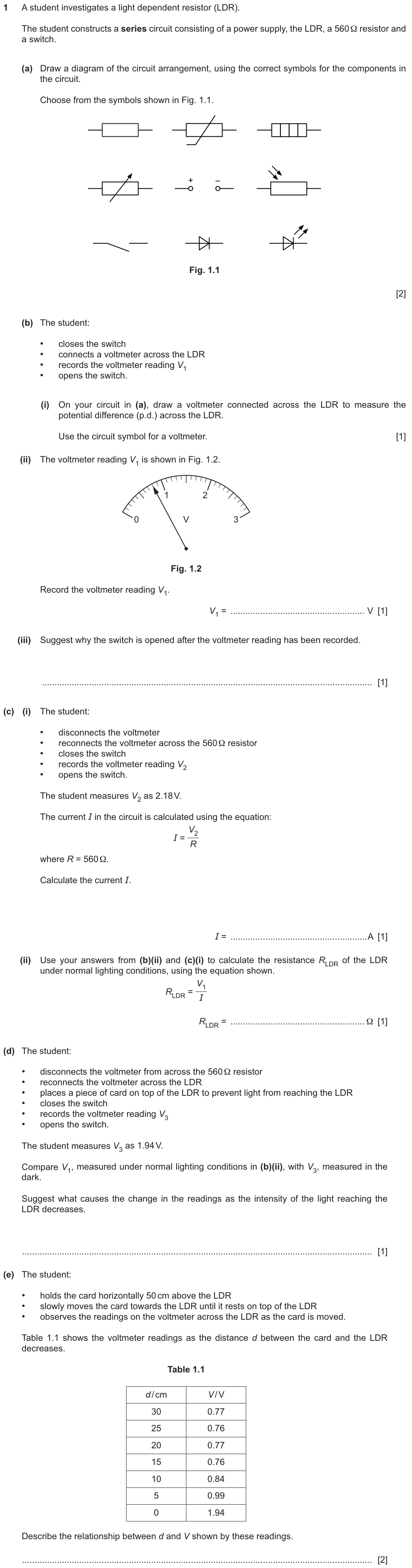
How to start: Draw the loop first (supply, switch, LDR, resistor), then the voltmeter across the LDR only. V1 is a meter reading (0.80 V); I comes from the OTHER voltmeter reading across the 560 Ω resistor.
✓ Show the answer have a go on paper first
- (a) One series loop: power supply, switch, LDR and the 560 Ω resistor, every symbol correct and nothing else.
- (b)(i) Voltmeter across the LDR (parallel).
The LDR and the 560 Ω resistor in one loop with the switch and supply; voltmeter across the LDR only. - (b)(ii) \(V_1=0.80\) V. (iii) To stop the battery running down / the components heating up.
- (c)(i) \(I=\dfrac{2.18}{560}=3.89\times10^{-3}\) A. (ii) \(R_{LDR}=\dfrac{0.80}{0.00389}=206\ \Omega\).
- (d) V across the LDR is larger in the dark (1.94 V > 0.80 V): the resistance of the LDR increases as the light decreases.
- (e) The reading stays about the same while the card is far away, then increases as the card gets close to the LDR.
| Part | Answer / working | Marks | Guidance |
|---|---|---|---|
| (a) | (any) series circuit drawn | B1 | |
| power supply, switch, LDR, resistor and no other components, in series, all symbols correct | B1 | ||
| (b)(i) | voltmeter connected in parallel across the LDR, symbol correct | B1 | |
| (b)(ii) | 0.8(0) (V) | B1 | |
| (b)(iii) | to stop the battery running down or the resistor / circuit / components heating up | B1 | |
| (c)(i) | 3.89 × 10⁻³ / 0.0039 (A) | B1 | |
| (c)(ii) | 205 / 206 / 210 (Ω) | B1 | |
| (d) | resistance of the LDR increases | B1 | |
| (e) | reading initially (more or less) constant as the distance decreases | B1 | |
| (then) increases as the card gets close to the LDR | B1 | ||
| Total: 10 marks | |||
Examiner tip (b)(iii) is the switch-off precaution in disguise: heating and battery life.
Past paper 2
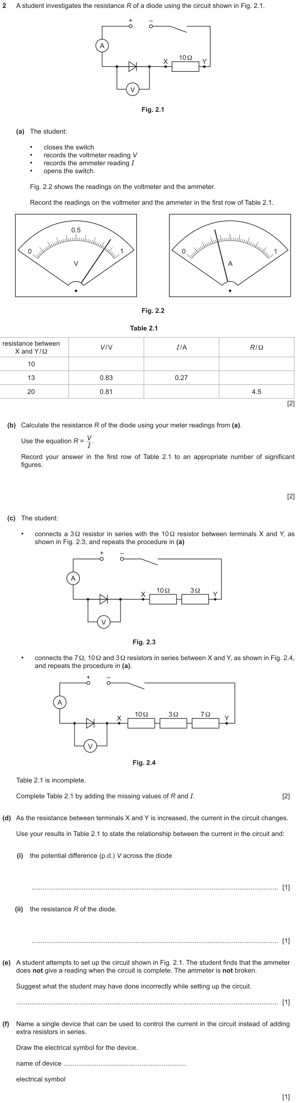
How to start: Read both meters first (count the divisions). Then every row is R = V/I or I = V/R. Part (d) wants each change linked to the current going DOWN.
✓ Show the answer have a go on paper first
- (a) \(V=0.84\) V, \(I=0.36\) A.
- (b) \(R=0.84\div0.36=2.33\to\) 2.3 Ω (2 s.f., like the readings).
- (c) 13 Ω row: \(R=0.83\div0.27=3.1\ \Omega\). 20 Ω row: \(I=0.81\div4.5=0.18\) A.
- (d)(i) As the current decreases, the p.d. across the diode stays (fairly) constant / decreases slightly. (ii) As the current decreases, the resistance of the diode increases.
- (e) The diode (or the power supply) was connected the wrong way round.
- (f) A variable resistor (rheostat) - the rectangle with an arrow through it, not the thermistor symbol.
| Part | Answer / working | Marks | Guidance |
|---|---|---|---|
| (a) | V = 0.84 (V) | B1 | |
| I = 0.36 (A) | B1 | ||
| (b) | 2.3(3…) | B1 | |
| 2.3 (Ω) | B1 | ||
| (c) | 3.1 (Ω) | B1 | |
| 0.18 (A) | B1 | ||
| (d)(i) | as the current decreases the p.d. across the diode remains (fairly) constant / decreases (slightly) | B1 | |
| (d)(ii) | as the current decreases the resistance increases | B1 | |
| (e) | diode / power supply / ammeter connected the wrong way round | B1 | |
| (f) | variable resistor and correct symbol | B1 | |
| Total: 10 marks | |||
Examiner tip The report: "directly / inversely proportional" earned nothing in (d) - describe each change linked to the current.
Describing how a component behaves
As the resistance between terminals X and Y is increased, the current in the circuit decreases. Use the results in Table 2.1 to describe what happens to: (i) the potential difference (p.d.) V across the diode (ii) the resistance R of the diode.
- "as the current decreases, the p.d. across the diode stays (fairly) constant"
- "as the current decreases, the resistance of the diode increases"
- "they are inversely proportional"
- "it increases" (no link to the current)
- describing changes against the resistance between X and Y
Each answer must tie the change to the variable that was changed (the current), in words, from the table. The report lists all three wrong versions.
From: 0625/62/M/J/24 Q2(d) scheme and examiner report
Type 1 Draw / complete a circuit
"Draw a diagram of the circuit … using the correct symbols." (2 marks)
Spot it a list of components.
- One series loop.
- Voltmeter across the component.
- Every symbol correct; nothing extra.
Type 2 R = V/I to s.f.
"Calculate R … to an appropriate number of significant figures." (2 marks)
Spot it V and I readings.
- R = V/I.
- Same s.f. as the readings (2 or 3).
Type 3 Precaution
"Suggest why the switch is opened after each reading." (1 mark)
Spot it "opens the switch".
- Stops the wire / component heating up, or the battery running down.
Type 4 Fault
"Suggest what the student has done wrong." (1 mark)
Spot it "the circuit did not work".
- Diode / supply wrong way round; voltmeter in series; loose connection.
Mistakes to avoid
- ✗ thermistor symbol for a variable resistor✓ rectangle with an arrow through it
- ✗ voltmeter in the main loop✓ voltmeter across the component
- ✗ "the switch was not closed" for a complete circuit that fails✓ "the diode was connected the wrong way round"Read what the question says is true.
- ✗ R = I/V✓ R = V/I
- ✗ "inversely proportional" as a description✓ "as the current decreases, R increases"
Summary
- Ammeter in series, voltmeter across; every symbol exact (variable resistor ≠ thermistor).
- R = V/I to 2-3 s.f.; resistance per length in Ω/cm.
- Lamp R rises with current; thermistor R falls with temperature; LDR R rises in the dark; diode conducts one way.
- Switch off between readings: no heating, no flat battery.
If you see …
- "correct symbols"check each one.
- "opens the switch"heating / battery.
- "did not work"diode or supply reversed.
Practice
Practice: easy, medium, hard
Easy
Show answer
Answer 6.0 Ω
Show answer
Answer in parallel
Show answer
Answer 8.0 Ω
Medium
Guide me
What is it asking? R per cm
What do we know? V, I, l
Plan R = V/I, then ÷ l
Show working
- R = 7.5 Ω
- 7.5 ÷ 60.0
Answer 0.125 Ω/cm
Guide me
What is it asking? total R
What do we know? parallel
Plan 1/R = 1/12 + 1/6
Show answer
Answer 4.0 Ω
Guide me
What is it asking? a practical reason
What do we know? short wire = small R
Plan large current
Show answer
Answer the current would be large, so the wire would get hot (or the ammeter would go off the scale)
Hard
Show working
- I = 1.65 ÷ 330 = 0.0050 A
- R = 2.40 ÷ 0.0050 = 480 Ω
Answer I = 5.0 × 10⁻³ A; R = 480 Ω
| Part | Answer / working | Marks | Guidance |
|---|---|---|---|
| I = 0.0050 A | B1 | ||
| 480 Ω | B1 | ||
| Total: 2 marks | |||
Show answer
Answer R rises from 5.0 Ω to 10 Ω: the resistance increases as the current increases
| Part | Answer / working | Marks | Guidance |
|---|---|---|---|
| 5.0 Ω and 10 Ω calculated | B1 | ||
| resistance increases as the current increases | B1 | ||
| Total: 2 marks | |||
Can I do this?
- I can draw every circuit symbol correctly, including variable resistor and thermistor.
- I connect ammeters in series and voltmeters in parallel.
- I can calculate R, R per unit length and series/parallel totals.
- I know how lamps, thermistors, LDRs and diodes behave in experiments.
- I can give the precautions and spot common faults.
Anything unticked: revise that section first. All ticked: take the quiz.
Quiz
The multiple-choice and guided questions need JavaScript. The concept checks and exam practice below work without it.
Your progress on this note is saved when JavaScript is on.