
Hardware
Logic gates and truth tables
What you need to be able to do
- 3.2Use and draw the symbols for NOT, AND, OR, NAND, NOR and XOR gates (all two-input except NOT).
- 3.2Describe the function of each gate and construct its truth table.
Next: Logic circuits, expressions and truth tables, where gates are combined.
Inside a processor every decision is made by logic gates: tiny electronic switches whose inputs and output are each 0 or 1 (low or high voltage). A truth table lists the output for every possible combination of inputs: 2 rows for one input, 4 for two, 8 for three.
The six gates
NOT
One input; the output is the opposite (inverse) of the input.
| A | Output |
|---|---|
| 0 | 1 |
| 1 | 0 |
AND
Output is 1 only when both inputs are 1.
| A | B | Output |
|---|---|---|
| 0 | 0 | 0 |
| 0 | 1 | 0 |
| 1 | 0 | 0 |
| 1 | 1 | 1 |
OR
Output is 1 when either or both inputs are 1; 0 only when both are 0.
| A | B | Output |
|---|---|---|
| 0 | 0 | 0 |
| 0 | 1 | 1 |
| 1 | 0 | 1 |
| 1 | 1 | 1 |
NAND
NOT AND: output is 0 only when both inputs are 1, otherwise 1.
| A | B | Output |
|---|---|---|
| 0 | 0 | 1 |
| 0 | 1 | 1 |
| 1 | 0 | 1 |
| 1 | 1 | 0 |
NOR
NOT OR: output is 1 only when both inputs are 0, otherwise 0.
| A | B | Output |
|---|---|---|
| 0 | 0 | 1 |
| 0 | 1 | 0 |
| 1 | 0 | 0 |
| 1 | 1 | 0 |
XOR
Exclusive OR: output is 1 when the inputs are different; 0 when they are the same.
| A | B | Output |
|---|---|---|
| 0 | 0 | 0 |
| 0 | 1 | 1 |
| 1 | 0 | 1 |
| 1 | 1 | 0 |
| Gate | Same as | How to remember it |
|---|---|---|
| NAND | NOT (A AND B) | AND's output column, flipped: 0 0 0 1 → 1 1 1 0 |
| NOR | NOT (A OR B) | OR's output column, flipped: 0 1 1 1 → 1 0 0 0 |
| XOR | (A OR B) AND NOT (A AND B) | “one or the other, but not both”: 0 1 1 0 |
Describing a gate in words
A description must cover every combination of inputs: say when the output is 1 (or 0) and that it is the other value otherwise.
1 NAND
Describe the operation of a NAND gate.
AskeddescriptionKnowAND flippedRoutewhen is it 0?
- The output is 0 only when both inputs are 1; otherwise the output is 1
“A NAND gate is the opposite of an AND gate” was not enough (June 2023): describe the outputs.
2 NOR
Describe the operation of a NOR gate.
AskeddescriptionKnowOR flippedRoutewhen is it 1?
- The output is 1 only when both inputs are 0; otherwise 0
3 XOR
Describe the operation of a 2-input XOR gate.
AskeddescriptionKnowexclusiveRoutedifferent inputs
- The output is 1 only if one input is 1 and the other is 0 (the inputs are different); 0 if they are the same
4 Which input gives 1?
Give one pair of inputs that makes a NOR gate output 1, and one that makes a NAND gate output 1.
Askedinput pairsKnowNOR: 1 only for 0,0; NAND: 1 unless 1,1Routeread the tables
- NOR: A = 0, B = 0 (the only pair)
- NAND: any pair except 1, 1, e.g. A = 0, B = 1
Mark-scheme focus
Describe the function of the NAND and NOR gates (2 marks)
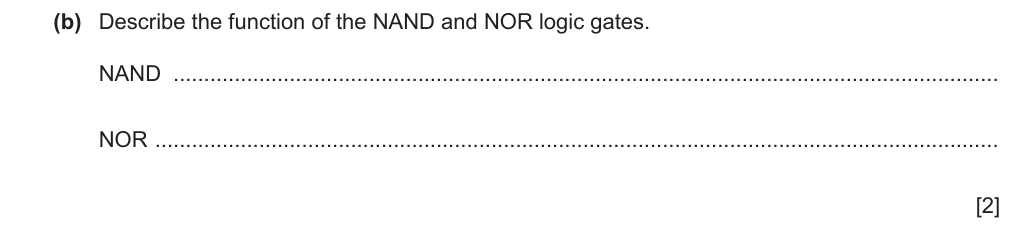
- NAND: 0 is only output when both inputs are 1 // 1 is output when none or one of the inputs is 1 B1
- NOR: 1 is only output when both inputs are 0 // 0 is output when one or both inputs are 1 B1
- “NAND is the opposite of AND” / “NOR is NOT OR” with no outputs
- Describing AND and OR instead
The function of a gate is its output for each input combination; “opposite of AND” leaves the examiner to work it out.
From: 9618/11/M/J/23 Q5(b)
Describe the operation of NAND, NOR, XOR and OR (4 marks)
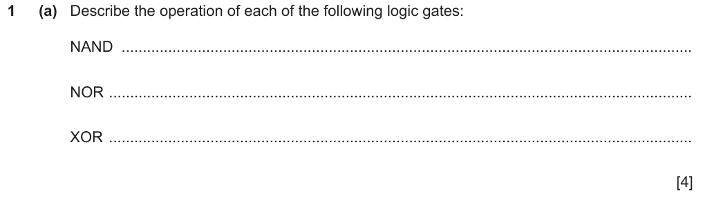
- NAND: the output is 0 when both inputs are 1, otherwise the output is 1 B1
- NOR: the output is 1 when both inputs are 0, otherwise 0 B1
- XOR: the output is 1 when one input is 1 and the other is 0, otherwise 0 B1
- OR: the output is 0 when both inputs are 0, otherwise 1 B1
- “OR: the output is 1 if one input is 1” (what if both are 1?)
- XOR described as OR
From: 9618/12/M/J/24 Q1(a)
- A gate question in almost every paper: describe gates (1-4 marks), tick / match the gate, complete gate truth tables, or give inputs for an output.
- Lost marks: NAND / NOR swapped, XOR confused with OR or NOR, careless symbols.
Worked examples
Example 1 · Which gate does each statement describe? (Paper 1, 3 marks) ★ Easy
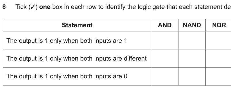
One tick per row - more than one scores nothing for that row (June 2021).
- only whenthe one case that gives 1
- Whole3 rows
- Rows
- both 1AND
- differentXOR
- both 0NOR
5 Now solve it have a go on paper first, then open the worked solution
- 1 only when both inputs are 1 → AND B1
- 1 only when both inputs are different → XOR B1
- 1 only when both inputs are 0 → NOR B1
Each statement picks out exactly one row of a 2-input truth table ✓.
Example 2 · One set of inputs for an output of 1 (Paper 1, 4 marks) ★★ Medium
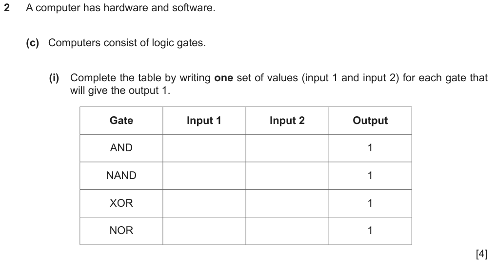
For each gate find a row of its truth table with output 1.
- (c)(i)4 rows
- Rows
- ANDonly 1,1
- NANDanything but 1,1
- XORdifferent
- NORonly 0,0
5 Now solve it have a go on paper first, then open the worked solution
- AND: 1, 1 B1
- NAND: 0, 0 or 0, 1 or 1, 0 B1
- XOR: 0, 1 or 1, 0 B1
- NOR: 0, 0 B1
Check each in the gate tables above ✓.
Example 3 · Truth tables for NOR and NAND (Paper 1, 2 marks) ★ Easy
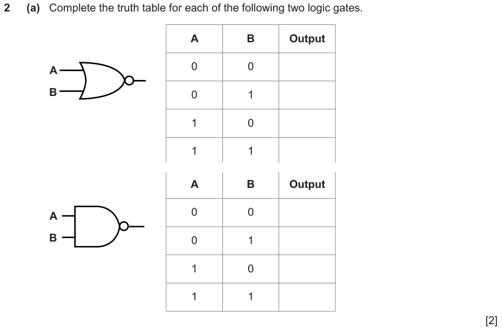
Identify each symbol first: a bubble on an OR shape is NOR; a bubble on an AND shape is NAND.
- the circleNOT on the output
- (a)two tables
5 Now solve it have a go on paper first, then open the worked solution
- First gate (OR shape + circle) = NOR: outputs 1, 0, 0, 0 B1
- Second gate (AND shape + circle) = NAND: outputs 1, 1, 1, 0 B1
The report: some candidates swapped the NAND and NOR tables ✓ - always identify the shape first.
Summary
| A | B | AND | OR | NAND | NOR | XOR |
|---|---|---|---|---|---|---|
| 0 | 0 | 0 | 0 | 1 | 1 | 0 |
| 0 | 1 | 0 | 1 | 1 | 0 | 1 |
| 1 | 0 | 0 | 1 | 1 | 0 | 1 |
| 1 | 1 | 1 | 1 | 0 | 0 | 0 |
- NOT inverts. NAND = AND then NOT; NOR = OR then NOT. XOR = 1 when the inputs differ.
- Describe a gate by its outputs for every input combination.
- Circle = NOT; extra input curve = XOR.
Can I do this?
- I can draw all six gate symbols clearly.
- I can write the truth table of each gate.
- I can describe each gate in words covering all inputs.
Anything unticked: revise that section first. All ticked: take the quiz.
Quiz
The multiple-choice and guided questions need JavaScript. The concept checks and exam practice below work without it.
Concept checks
Answer each one in your head first, then open it.
1Why are NAND and NOR called universal gates?Show answer
Any other gate (and so any circuit) can be built from NAND gates alone, or NOR gates alone: e.g. A NAND A = NOT A. That is why flash memory is built from NAND or NOR cells.
2How many rows does a truth table with 4 inputs need?Show answer
2⁴ = 16: each extra input doubles the rows.
Exam-style practice
New questions, not used above. Do them on paper, then mark your work against the official mark scheme.

Show the mark scheme
| Part | Answer / working | Marks | Guidance |
|---|---|---|---|
| (a) | Output is only 1 if one input is 1 and the other is 0 // only 1 if both inputs are different // only 0 if both inputs are the same | B1 | |
| Total: 1 mark | |||
Draw the symbol and complete the truth table for a NAND gate, then state one pair of inputs for which its output is 0.
- [3]
Show the mark scheme
| Part | Answer / working | Marks | Guidance |
|---|---|---|---|
| AND-shaped symbol with a circle on the output | B1 | ||
| Outputs 1, 1, 1, 0 (inputs 00, 01, 10, 11) | B1 | ||
| Output 0 only for A = 1, B = 1 | B1 | ||
| Total: 3 marks | |||
Your progress on this note is saved when JavaScript is on.