
Forces, density and pressure
Equilibrium: the principle of moments and vector triangles
What you need to be able to do
- 4.2.1State and apply the principle of moments.
- 4.2.2Understand that when there is no resultant force and no resultant torque, a system is in equilibrium.
- 4.2.3Use a vector triangle to represent coplanar forces in equilibrium.
Before you start: Moments and couples. Next: Density and pressure.
The two conditions for equilibrium
Resultant force = 0
No acceleration: at rest or moving at constant velocity (first law). In practice: upward forces = downward forces and left = right.
Resultant torque = 0
No turning: clockwise moments = anticlockwise moments about any point you choose.
You need both. A couple has zero resultant force but turns the object; a single push through the centre of gravity has no moment but accelerates it. In each case the object is not in equilibrium (9702/13/M/J/24 Q12: two forces alone can only balance if they are equal and act along the same line).
The principle of moments
Because the resultant moment is zero about every point, you may choose the point. Choose it cleverly: a force that passes through your chosen point has no moment about it, so it drops out of the equation. That is how you get rid of an unknown force.
How to solve a beam / hinge / rod question
- Draw every force on the object: weight at the centre of gravity (the middle if uniform), loads, tensions, and the force at the hinge/pivot/support.
- Choose the point to take moments about: the one where the unknown force you don't want acts (usually the hinge).
- For each force, work out its moment: force × perpendicular distance from the point (resolve slanted forces first: only the part at 90° to the beam counts). Mark each as clockwise or anticlockwise.
- Sum of clockwise = sum of anticlockwise, and solve. C1 C1 A1
- For the force at the hinge, resolve: up = down (vertical component) and left = right (horizontal component). Combine with Pythagoras if the whole force is asked.
- Check: the hinge force often points away from the wall and partly up — it balances the horizontal pull of the string.
Case by case
1 Beam on two supports: find a support force
A 9.0 m uniform beam (380 N) rests on supports B (2.0 m from A) and C (2.0 m from D). A man (750 N) stands 3.6 m from D. Find FB. 9702/22/O/N/19 Q4(b)(ii)
Askedforce at support BKnowall weights and positionsRoutemoments about the OTHER support C, every distance from C
- Moments about C (removes FC). Distances from C: B 5.0 m, beam's centre 2.5 m, man 1.6 m.
- FB × 5.0 = 380 × 2.5 + 750 × 1.6
- FB = 2150 / 5.0 = 430 N; then FC = 380 + 750 − 430 = 700 N (up = down).
2 About to tip
Same beam: the man walks towards D. How close to D can he stand? 9702/22/O/N/19 Q4(b)(iii)
Askedhow close to D he can standKnowbeam about to tipRouteabout to tip → FB = 0; moments about C
- "About to tip" means the other support stops pushing: FB = 0.
- Moments about C: 380 × 2.5 = 750 × (2.0 − x)
- 2.0 − x = 1.27 → x = 0.7 m from D.
The November 2019 report: most found this challenging; many kept a moment for FB, or gave the distance from C instead of from D.
3 Hinged rod held by an angled wire
A uniform rod XY (10.0 N) hinged at X is held horizontal by a force F at Y at 30° to the horizontal. Find F. 9702/12/M/J/23 Q12
Askedthe force F at YKnowrod weight, F at 30°Routemoments about the hinge; only F sin 30° turns the rod
- Moments about X. The rod's weight acts at the middle: 10.0 × L/2.
- Only F's vertical part, F sin 30°, has a moment, at distance L: F sin 30° × L.
- F × 0.5 × L = 10.0 × 0.5 × L → F = 10 N. (20 N, the popular wrong answer, puts the weight at Y.)
4 Moving a load: increase or decrease?
The block on a hinged beam is moved closer to the hinge. What happens to the horizontal force at the hinge? 9702/22/F/M/23 Q3(e)
Askedchange in hinge horizontal forceKnowblock moved towards the hingeRoutechain: block's moment ↓ → tension ↓ → its horizontal part ↓
- The block's moment about the hinge falls (smaller distance).
- So the string's moment must fall: the tension decreases, and so does its horizontal component.
- The hinge's horizontal force balances that component, so it decreases.
The March 2023 report: "a significant number of the stronger candidates incorrectly stated that there would be no effect".
5 A force with no moment
Why does the force at B have no moment about A? 9702/22/M/J/19 Q3(b)(ii)
Askedwhy the force at B has no moment about AKnowmoment = F × perpendicular distanceRouteits line passes through A → distance 0 → moment 0
- Moment = force × perpendicular distance.
- The line of action of the force at B passes through A, so the perpendicular distance is zero.
- So its moment about A is zero, whatever its size.
Three forces in equilibrium: the vector triangle
If three coplanar forces keep an object in equilibrium, their resultant is zero, so drawn tip to tail they make a closed triangle. (Their lines of action also pass through one point; otherwise they would form a turning effect.)
- Draw the known force (usually the weight) to scale or as a labelled line, with its arrow.
- From its tip, draw the next force's direction; from the start, draw the third force's direction (backwards). Where they meet closes the triangle.
- Arrows go round the triangle one way (tip to tail all round) — the 2018 reports say candidates chose diagrams where two arrows met head to head.
- Solve: right-angled → trig (T = W / cos 18° = 547 N; R = T sin 18° = 169 N); otherwise sine/cosine rule; or measure a scale drawing (marks for ±1°/±3% usually).
Or resolve instead: up = down and left = right give two equations for two unknowns. The mark schemes accept either method. For the climber: T cos 18° = 520 and T sin 18° = R.
Mark-scheme focus
State the principle of moments
State the principle of moments.
- "in (rotational) equilibrium"
- "sum / total of clockwise moments about a point = sum / total of anticlockwise moments about the (same) point"
- "clockwise moments = anticlockwise moments" (no sum, no point)
- "... for a closed / isolated system" (that's momentum)
- a definition of the moment of a force
The March 2025 report: "very few fully correct answers ... many did not explicitly state that these moments are about the same point ... only the stronger candidates stated that this was for an object in rotational equilibrium".
From: 9702/22/F/M/25 Q2(a), 9702/23/O/N/24 Q3(a), 9702/22/O/N/19 Q4(b)(i) and their reports. Paper 1: 9702/13/O/N/22 Q12 ("about the same point").
State the two conditions for equilibrium
State two conditions for an object to be in equilibrium.
- "resultant force (in any direction) is zero"
- "resultant moment / torque (about any point) is zero"
- "no forces act" / "the forces are balanced" without "resultant"
- "the resultant turning effect is zero" ("turning effect" is not a physical quantity)
- "it is not moving"
From: 9702/22/F/M/23 Q3(a), 9702/23/O/N/23 Q3(a) and the March 2023 report.
Explain why a force must act on the rod at the wall
A uniform rod is attached to a wall at A and held horizontal by a string from B at an angle. Use the concept of equilibrium to explain why a force must act on the rod at A.
- "(for equilibrium) resultant force (and moment) = 0"
- "the horizontal component of T is not balanced by the other forces shown" (or: upward ≠ downward forces)
- "to stop the rod falling" (no physics)
- "Newton's third law: the rod pushes the wall"
- Moments about a hinge or pivot with a slanted string: the commonest Paper 2 question in this chapter (2-3 marks, C1 for one moment, C1 for two, A1).
- Force at the hinge / support by resolving: 1 mark, often missed.
- "Increase, decrease or no effect?" after moving a load: 1 mark, hard.
- Vector triangles: Paper 1 every year (which triangle? hinge force direction?), Paper 2 scale drawings occasionally.
Worked examples
Example 1 · Beam, hinge and string (Paper 2, 7 marks) ★★ Medium
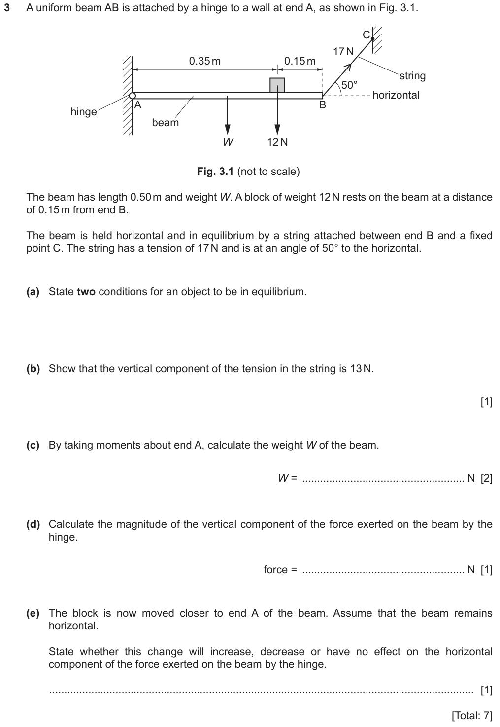
A beam is hinged at one end and held level by a slanted string at the other. A block sits on it. Everything is still, so both equilibrium conditions hold. We use moments to find the beam's weight, then up = down for the hinge force.
- uniformthe beam's weight acts at its middle, 0.25 m from A
- at 50° to the horizontalonly the string's VERTICAL component turns the beam about A
- By taking moments about Athe hinge force acts at A, so it drops out of the equation
- vertical component of the hinge forceafter moments: total up = total down
- State the effectincrease / decrease / no change, following the chain of moments
- (a)two conditions for equilibrium
- (b)show vertical tension = 13 N
- (c)the beam's weight W
- (d)vertical hinge force
- (e)effect of moving the block towards A
- L = 0.50 mbeam
- 12 N block0.15 m from B → 0.35 m from A
- T = 17 Nat B, 50° to horizontal
- (c) FindW
- Usemoments about A: W × 0.25 + 12 × 0.35 = 13 × 0.50
- Needs13 N from (b)
- Trapthe block's distance is from A: 0.50 − 0.15
- Usemoments about A: W × 0.25 + 12 × 0.35 = 13 × 0.50
- (d) Findhinge vertical force
- Useup = down: F + 13 = W + 12
- NeedsW from (c)
- Useup = down: F + 13 = W + 12
- (e) Decidehinge horizontal force
- Chainblock's moment ↓ → tension ↓ → its horizontal part ↓ → hinge's horizontal force ↓
Why take moments about A rather than B?
The hinge force at A is unknown in both size and direction. At A its moment is zero, so the only unknown left is W.
Once W is known, do we need moments again for the hinge?
No. Vertical forces balance: hinge (up) + 13 (up) = W + 12 (down). One line.
5 Now solve it have a go on paper first, then open the worked solution
- (a) Resultant force zero; resultant moment zero B1 B1
- (b) 17 sin 50° = 13 N A1 The vertical side is opposite the 50° angle with the horizontal.
- (c) Moments about A: W at 0.25 m (middle), block at 0.50 − 0.15 = 0.35 m, string's 13 N at 0.50 m: (W × 0.25) + (12 × 0.35) = 13 × 0.50 C1
- W = (6.5 − 4.2) / 0.25 = 9.2 N A1
- (d) Up = down: F + 13 = 9.2 + 12 → F = 8 N A1 (only a small minority saw this, March 2023 report)
- (e) Decrease B1 — see Case 4 above for the chain.
W (9.2 N) and the hinge force (8 N) are both positive and of sensible size; 8 + 13 = 21 ≈ 9.2 + 12 ✓.
Example 2 · Wire at 37°: weight of a block and the hinge force (Paper 2, 6 marks) ★★ Medium
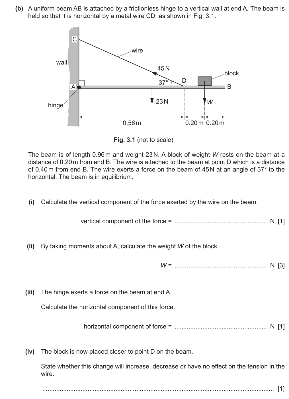
A hinged beam carries a block and is held up by a wire pulling at 37°. We find the vertical part of the wire's pull, use moments about the hinge to find the block's weight, and balance the horizontal forces for the hinge.
- uniform … 0.96 mthe beam's weight acts 0.48 m from A
- 0.20 m from B, 0.40 m from Bconvert every position into a distance from A
- at 37° to the horizontalvertical part 45 sin 37°, horizontal part 45 cos 37°
- horizontal component of the hinge forceonly the wire and hinge act horizontally - they balance
- (i)vertical component of the wire's force
- (ii)the block's weight W
- (iii)horizontal hinge force
- (iv)tension if the block moves towards D
- L = 0.96 m, 23 Nbeam
- block W0.76 m from A
- wire 45 N at D0.56 m from A, 37°
- (ii) FindW
- Usemoments about A: 23 × 0.48 + W × 0.76 = 27 × 0.56
- Needs27 N from (i)
- Distancesall measured from A
- Usemoments about A: 23 × 0.48 + W × 0.76 = 27 × 0.56
- (iii) Findhinge horizontal
- Usehorizontal balance: = 45 cos 37°
- Trapit is NOT zero - the wire pulls sideways
- Usehorizontal balance: = 45 cos 37°
- (iv) Decidetension
- Chainblock nearer A → smaller moment → smaller tension needed
The question gives distances from B. What do we do first?
Turn them into distances from A (the pivot): 0.96 − 0.20 = 0.76 m and 0.96 − 0.40 = 0.56 m.
Which forces act horizontally on the beam?
Only the wire's horizontal part and the hinge. The weights are vertical. So the hinge must push back with 45 cos 37°.
5 Now solve it have a go on paper first, then open the worked solution
- (i) 45 sin 37° = 27 N A1 (the common error was the horizontal component)
- (ii) Distances from A: beam's centre 0.48 m, D 0.96 − 0.40 = 0.56 m, block 0.96 − 0.20 = 0.76 m C1 C1
- (23 × 0.48) + (W × 0.76) = 27 × 0.56 → W = (15.1 − 11.0) / 0.76 = 5.4 N A1
- (iii) Horizontally only the wire and the hinge act: 45 cos 37° = 36 N A1 (many assumed it was zero)
- (iv) Closer to D means closer to A: smaller moment, so the tension decreases B1
W (5.4 N) is smaller than the beam's own weight - believable for a small block; a negative W would mean a mixed-up distance.
Example 3 · Beam on two pivots, about to tip (Paper 2, 6 marks) ★★★ Hard
Why it is hard: the November 2019 report: many found the distances from C difficult, and in (iii) kept a moment for FB or gave the distance from C.
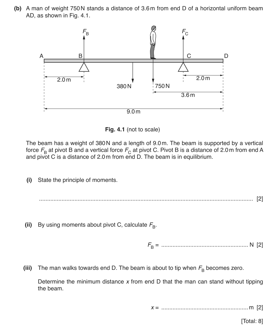
A heavy beam rests on two supports B and C. A man stands on it. First we find the force at B. Then the man walks towards the end D, beyond C; at some point the beam starts to tip about C - at that moment B stops pushing.
- State the principle of momentsinclude 'in equilibrium' and 'about the SAME point'
- By using moments about CFC drops out; measure every distance from C
- about to tipthe far support stops pushing: FB = 0
- minimum distance x from Dthe answer is measured from D, not from C
- (i)principle of moments
- (ii)force at B
- (iii)how close to D the man can stand
- 9.0 m, 380 Nbeam, centre 4.5 m from A
- B: 2.0 m from A
- C: 2.0 m from D7.0 m from A
- man 750 N3.6 m from D
- distances from C: B 5.0 m, centre 2.5 m, man 1.6 m
- (ii) FindFB
- Usemoments about C: FB × 5.0 = 380 × 2.5 + 750 × 1.6
- Work out firsteach distance from C
- Usemoments about C: FB × 5.0 = 380 × 2.5 + 750 × 1.6
- (iii) Findx
- Useabout to tip → FB = 0, moments about C
- Balance380 × 2.5 = 750 × (2.0 − x)
- Trapx is from D: the man is (2.0 − x) from C
- Useabout to tip → FB = 0, moments about C
What happens to FB as the man walks towards D?
It gets smaller - his moment about C increasingly balances the beam's weight. When it reaches zero, the beam is about to lift off B.
Where is the man when he is 'x from D'?
C is 2.0 m from D, so he is (2.0 − x) m beyond C on the other side from the beam's centre.
5 Now solve it have a go on paper first, then open the worked solution
- (i) For a body in equilibrium, sum of clockwise moments about a point = sum of anticlockwise moments about the same point B1 B1
- (ii) Distances from C: B 5.0 m, centre (4.5 m from A) 2.5 m, man (5.4 m from A) 1.6 m. FB × 5.0 = 380 × 2.5 + 750 × 1.6 C1 → FB = 430 N A1
- (iii) Tipping: FB = 0, so only the beam (one side of C) and the man (other side) have moments about C: 380 × 2.5 = 750 × (2.0 − x) C1 → x = 0.7 m A1
x = 0.7 m is between 0 and 2.0 m - he gets to within 0.7 m of the end. If x came out bigger than 2.0, he'd be on the wrong side of C.
Example 4 · A tree supported by a post (Paper 2, 7 marks) ★★★ Hard
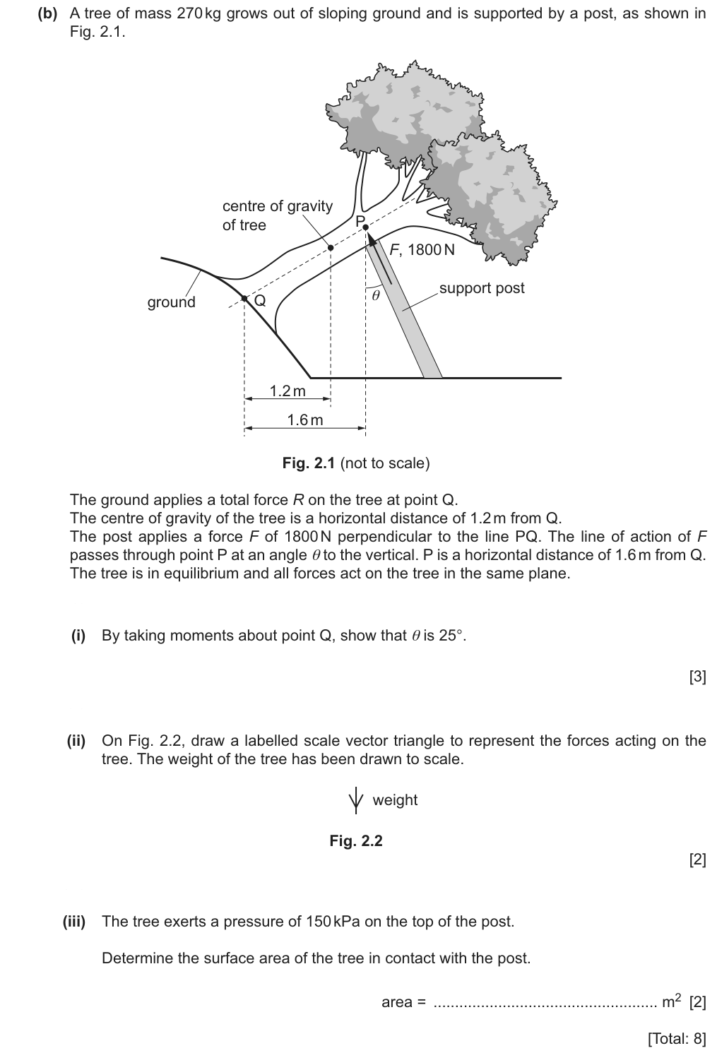
A tree on a slope is propped up by a post pushing at right angles to the line PQ. The tree's weight tries to turn it about Q; the post's push turns it back. Balancing moments about Q gives the post's angle. Then pressure gives the contact area.
- By taking moments about Qthe ground's force R acts at Q, so it drops out
- 1.2 m horizontally from Qthe weight is vertical, so 1.2 m IS its perpendicular distance
- perpendicular to PQthe post force's moment arm is the length PQ itself
- 150 kPa150 × 103 Pa; area = force ÷ pressure
- (i)show θ = 25°
- (ii)scale vector triangle
- (iii)contact area
- m = 270 kgtree
- 1.2 mc.g. horizontally from Q
- F = 1800 N⟂ to PQ, at P
- 1.6 mP horizontally from Q
- p = 150 kPaon the post
- PQ is tilted at θ to the horizontal, so its length is 1.6 ÷ cos θ
- (i) Showθ = 25°
- Usemoments about Q: W × 1.2 = F × PQ
- W270 × 9.81
- PQ1.6 ÷ cos θ
- Usemoments about Q: W × 1.2 = F × PQ
- (iii) Findarea
- UseA = F ÷ p
- UnitskPa → Pa
- UseA = F ÷ p
For a force perpendicular to PQ, what is its moment arm about Q?
The length PQ - the force already meets the line at 90°, so the distance along PQ is the perpendicular distance.
How do we get PQ from the 1.6 m horizontal distance?
1.6 m is the horizontal side of a triangle whose slanted side is PQ at angle θ: PQ = 1.6 ÷ cos θ.
5 Now solve it have a go on paper first, then open the worked solution
- (i) Moment of the weight about Q: 270 × 9.81 × 1.2 = 3180 N m B1
- F is perpendicular to PQ, so its perpendicular distance from Q is the length PQ. P is 1.6 m horizontally from Q and PQ is tilted at θ to the horizontal, so PQ = 1.6 / cos θ: moment = 1800 × 1.6 / cos θ B1
- 1800 × 1.6 / cos θ = 3180 → cos θ = 0.906 → θ = 25° B1
- (ii) Closed tip-to-tail triangle of W (drawn), F at 25° to the vertical and R closing it M1 A1
- (iii) A = F / p = 1800 / 150 × 103 = 0.012 m² C1 A1
No examiner report exists yet for June 2025. The key idea in (i): when a force is perpendicular to a line through the pivot, its moment arm is simply the length along that line.
cos θ = 0.906 gives 25°, matching the 'show that'. Area 0.012 m² is about 11 cm square - a sensible post top.
Example 5 · A climber on a rope: the vector triangle (Paper 2, 7 marks) ★★ Medium
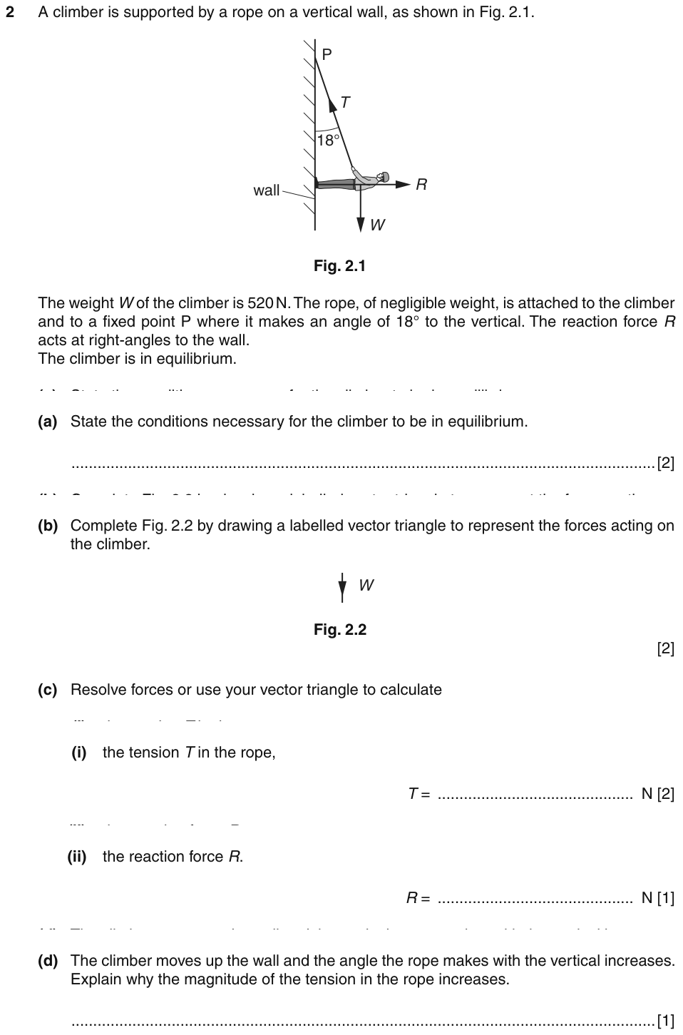
A climber hangs from a rope at a small angle to the vertical, pushing off a wall that pushes back horizontally. Three forces, in equilibrium: they form a closed triangle, which gives the tension and the wall's force.
- conditions for equilibriumresultant force zero AND resultant moment zero
- vector triangledraw the three forces tip-to-tail; it closes because the resultant is zero
- 18° to the verticalthe angle between T and W in the triangle
- R is horizontalR and W are at 90°: a right-angled triangle
- (b)labelled vector triangle
- (c)(i)the tension T
- (c)(ii)the wall's force R
- (d)why T rises with the angle
- W = 520 Ndown
- rope at 18°to the vertical
- R horizontal
- (c)(i) FindT
- Usevertical balance: T cos 18° = W
- (c)(ii) FindR
- Usehorizontal balance: R = T sin 18°
- NeedsT from (c)(i)
- Usehorizontal balance: R = T sin 18°
- (d) ExplainT and angle
- UseT = W ÷ cos θ, and cos θ falls as θ grows
Which force holds up the climber's weight?
Only the rope's vertical part, T cos 18°. R is horizontal and does nothing vertically.
Is T bigger or smaller than the weight?
Slightly bigger - only part of T acts upwards, so T must exceed 520 N.
5 Now solve it have a go on paper first, then open the worked solution
- (b) Triangle as drawn above: W down, R horizontal, T closing it at 18° to W M1 A1
- (c)(i) T cos 18° = W → T = 520 / cos 18° = 547 N C1 A1
- (ii) R = T sin 18° = 169 N A1
- (d) T = W / cos θ; as θ increases, cos θ decreases, so T increases M1
T (547 N) is just above W, as expected for a small angle; R (169 N) is much smaller than W.
Example 6 · The crane jib (Paper 1, 1 mark) ★★★ Hard
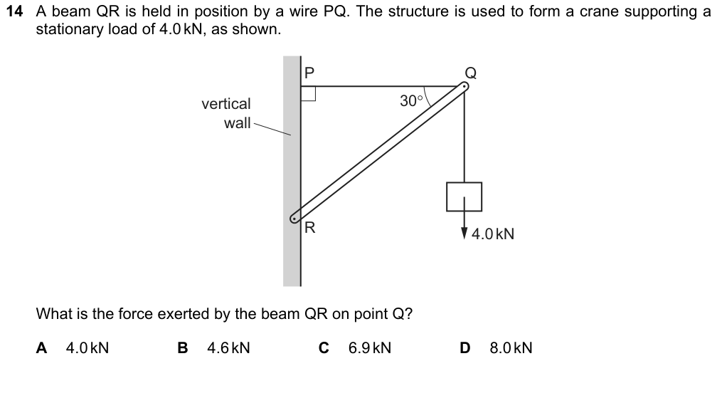
Why it is hard: the November 2021 report: many chose A. Three forces act on point Q: the horizontal wire, the 4.0 kN load and the beam's push along the beam.
A load hangs from point Q, held by a horizontal wire and a slanted beam. We need how hard the beam pushes on Q.
- horizontal wireit can't hold anything UP - it only pulls sideways
- beam … at 30° to the horizontalthe beam's force acts along the beam; its vertical part is F sin 30°
- force the beam exerts on Qlook at point Q in equilibrium: three forces
- the beam's force on Q
- load = 4.0 kNdown at Q
- beam at 30°to the horizontal
- wirehorizontal
- FindF (beam)
- Usevertical balance at Q: F sin 30° = 4.0 kN
- TrapF is NOT 4.0 kN - only part of it acts upwards
- Usevertical balance at Q: F sin 30° = 4.0 kN
Which of the three forces can hold the load up?
Only the beam - the wire is horizontal. So the beam's vertical component must equal the whole 4.0 kN.
If only half of F acts upwards (sin 30° = 0.5), how big must F be?
Twice the load: 8.0 kN.
5 Now solve it have a go on paper first, then open the worked solution
- Only the beam's force has a vertical component to hold up the load (the wire is horizontal).
- F sin 30° = 4.0 kN
- F = 8.0 kN → D (and the wire's tension = F cos 30° = 6.9 kN, which is option C)
F (8.0 kN) is bigger than the load because the beam is shallow; the wire then pulls F cos 30° = 6.9 kN - that's option C, the trap.
Summary
- Equilibrium = resultant force zero AND resultant moment zero.
- Principle of moments: in equilibrium, sum of clockwise = sum of anticlockwise moments about the same point.
- Take moments about the unknown force you want to eliminate; then resolve for the hinge/support force.
- Three forces in equilibrium form a closed tip-to-tail triangle (or resolve).
| If you see… | do this |
|---|---|
| "by taking moments about A" | forces through A drop out; perpendicular distances from A |
| "force at the hinge" | resolve: vertical and horizontal components separately |
| "about to tip" / "just lifts" | the support that is losing contact exerts zero force |
| three forces, object at rest | closed vector triangle, or two resolving equations |
| "increase, decrease or no effect" | follow the chain: moment → tension → its component → the other force |
Can I do this?
- I can state both conditions for equilibrium with "resultant".
- I can state the principle of moments fully (sum, same point, equilibrium).
- I can choose the point, find each moment and solve, then resolve for the hinge force.
- I can handle two supports, tipping, angled wires and "what if the load moves".
- I can draw and solve a vector triangle for three forces.
Anything unticked: revise that section first. All ticked: take the quiz.
Quiz
Your progress on this note is saved when JavaScript is on.