
Practical skills: Paper 6 Alternative to Practical
Optics experiments: ray tracing, blocks and lenses
In this note
- AO3Draw a normal, mark rays with pins (or a ray box), and measure angles with a protractor to the nearest degree.
- AO3Use the techniques that make a ray trace accurate: pins far apart, vertical, view the bases, thin lines.
- AO3Investigate reflection (i = r, image position) and refraction through rectangular, semicircular and triangular blocks.
- AO3Find the focal length of a converging lens and the magnification of an image; describe the image.
- AO3Classify materials as transparent, translucent or opaque from what they do to light.
The skills used here: readings and scale drawings, the 10% rule.
Rules to learn
Ray tracing with pins or a ray box
General methodHow to trace any ray with pins
- Draw the outline of the mirror or block on the ray-trace sheet; draw the normal at 90° (protractor or set square).
- Draw the incident ray at the angle asked for (protractor at the point where the normal meets the surface).
- Stick pins P1 and P2 upright on the incident ray, at least 5 cm apart.
- Look from the other side so P1 and P2 (or their images) line up; put P3 and P4 so all four appear in one straight line - look at the bases of the pins.
- Remove the pins, draw a line through P3 and P4, and measure the angle with a protractor.
| Technique | Why it helps |
|---|---|
| pins far apart (≥ 5 cm) | a small error in placing a pin makes only a small error in the angle of the line |
| pins vertical; view the bases of the pins | the tops can lean and look lined up when the bases are not |
| thin, sharp pencil lines | a thick line hides where the ray is |
| thin pins | easier to line up exactly |
| with a ray box: a narrow slit, a darkened room, crosses marked in the centre of the ray | the ray has a width: its centre is hard to mark |
Reflection in a plane mirror
Measure both angles from the normal. To find the image position, draw lines back through two reflected rays behind the mirror: they meet at the image, the same distance behind the mirror as the object is in front.
A source of error the scheme accepts: the reflecting surface is the silvered BACK of a glass mirror, not the front line you drew on.
Try it yourself
Show answer
Answer 55°
Refraction through blocks
General methodHow to find the refracted ray inside a block
- Draw round the block; draw the normal where the incident ray enters.
- Pins P1, P2 on the incident ray; look through the block and place P3, P4 in line with the images.
- Remove the block; draw the emergent ray through P3 and P4 back to the block edge.
- Join the entry point to the exit point: that is the refracted ray inside.
- Measure the angle of refraction r between it and the normal; repeat for other angles of incidence.
| Block | What the experiment shows |
|---|---|
| rectangular | emergent ray parallel to the incident ray; sideways shift |
| semicircular (ray aimed at the centre of the flat face) | the ray enters the curved face along a radius undeviated; at the flat face it refracts, or totally internally reflects above the critical angle |
| triangular prism | the ray is deviated towards the base; white light spreads into a spectrum |
Example i = 40°, r = 25°. Refractive index (2 d.p.)?
n = sin i / sin r.
- \(\sin40^\circ=0.643\), \(\sin25^\circ=0.423\)
- \(n=0.643\div0.423=1.52\)
Answer 1.52
Try it yourself
Show answer
Answer 1.53
Lenses: focal length, images and magnification
| Method | How | Accuracy tips |
|---|---|---|
| distant object | focus the image of a far window on a screen; f = lens-to-screen distance | object at least 10 times further than f; measure to the centre of the lens |
| object and screen | fixed object-to-screen distance D; move the lens until the image is sharp; measure u and v | darkened room / bright object; move the screen (or lens) slowly back and forth to find the sharpest image; lens and screen perpendicular to the bench |
| magnification | measure the image height and the object height | measure the same features (e.g. height of the arrow) |
Describe a real image on a screen in the scheme's words: inverted (upside down), and magnified (larger) or diminished (smaller). The arrow shape on the lamp also comes out laterally inverted (reversed left to right).
Example u = 15.0 cm, v = 30.0 cm. Use \(\tfrac1f=\tfrac1u+\tfrac1v\) and find f; also the magnification.
Substitute, then m = v/u.
- \(\tfrac1f=\tfrac1{15.0}+\tfrac1{30.0}=0.100\)
- \(f=10.0\) cm
- \(m=30.0\div15.0=2.0\)
Answer f = 10.0 cm; magnified 2.0 times
Try it yourself
Show answer
Answer 4.0
Transparent, translucent and opaque
| Material | What it does to light | How to test |
|---|---|---|
| transparent (glass, clear Perspex) | lets light through; you can see clearly through it | a clear image of a pin or lamp through it |
| translucent (tracing paper, frosted glass) | lets light through but scatters it; no clear image | light gets through, shapes are blurred |
| opaque (card, metal) | lets no light through | no light reaches the screen |
From the past papers
Past paper 1
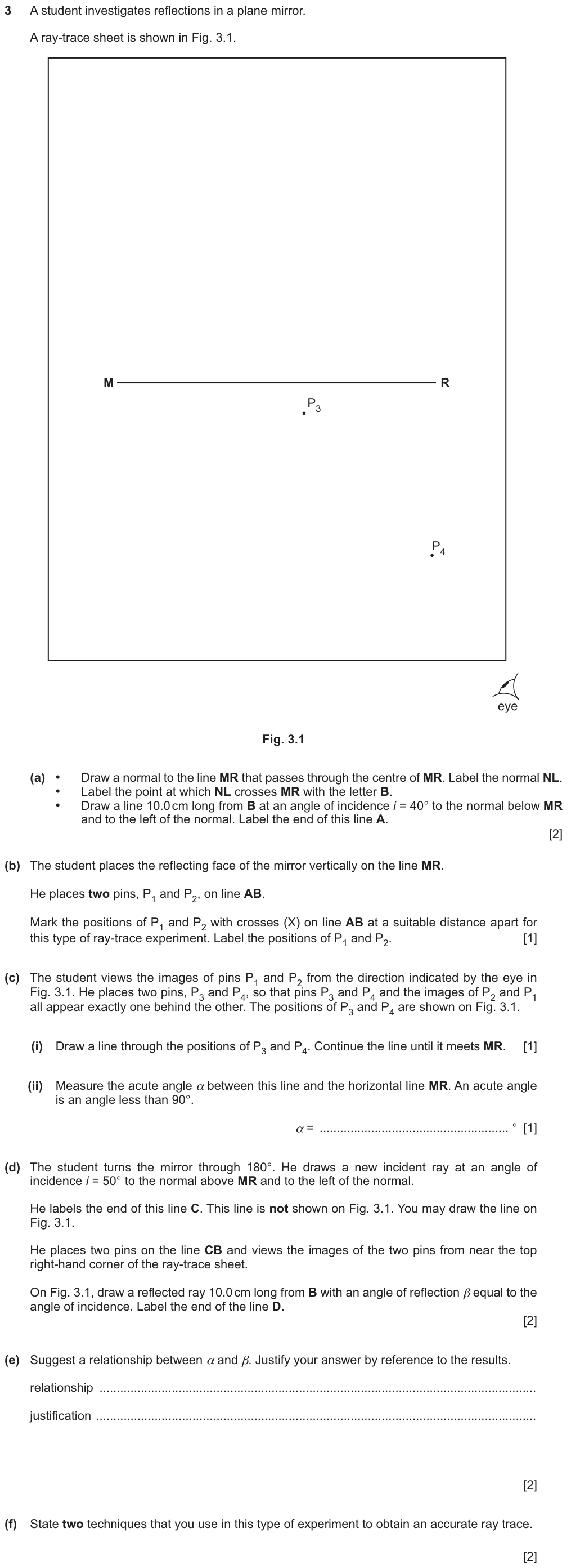
How to start: On paper you would draw on Fig. 3.1. Here, think it through: the normal is at 90° to MR, angles of incidence are measured from the normal, and the pins go as far apart as the 10 cm line allows.
✓ Show the answer have a go on paper first
- (a) Normal at 90° to MR through its centre, labelled NL, B where it crosses; AB drawn 10.0 cm long at 40° to the normal, below MR and to its left.
- (b) P1 and P2 on AB, at least 5.0 cm apart.
- (c)(i) The line through P3 and P4 meets MR at B. (ii) α = 48° (the scheme allows ±2°).
- (d) Reflected ray from B at β = 50° to the normal, above MR on the right, 10.0 cm long.
- (e) α and β are equal: 48° and 50° differ by 4%, within the limits of experimental accuracy (10%).
- (f) Any two: thin pins; thin lines / a sharp pencil; view the bases of the pins / pins vertical; pins far apart (at least 5 cm).
| Part | Answer / working | Marks | Guidance |
|---|---|---|---|
| (a) | normal neat and at 90° | B1 | |
| incident ray in the correct quadrant at 40° ± 2° | B1 | ||
| (b) | P1 P2 separation at least 5.0 cm | B1 | |
| (c)(i) | incident ray, reflected ray and normal meeting at B within 2 mm | B1 | |
| (c)(ii) | α = 48° ± 2° | B1 | |
| (d) | new reflected ray above MR in an appropriate quadrant | B1 | |
| angle of reflection drawn 50° ± 2° | B1 | ||
| (e) | statement to match the results | B1 | |
| justification: equal within the limits of experimental error, OR unequal if beyond | B1 | ||
| (f) | any two: thin pins · thin lines / sharp pencil · view bases of pins / pins vertical · pins far apart / at least 5 cm | B2 | |
| Total: 11 marks | |||
Examiner tip Six of the eleven marks are drawing accuracy on the sheet: a sharp pencil, a ruler and a protractor used carefully are worth more than any explanation.
Past paper 2
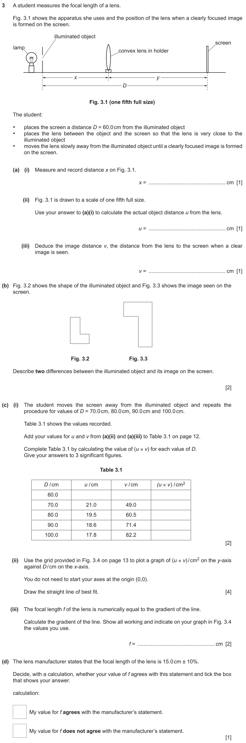
How to start: Fig. 3.1 is ONE FIFTH full size: the measured x (4.8 cm) times 5 is u. Then v = D − u. The gradient of (u × v) against D is f.
✓ Show the answer have a go on paper first
- (a)(i) \(x=4.8\) cm. (ii) \(u=4.8\times5=24.0\) cm. (iii) \(v=60.0-24.0=36.0\) cm.
- (b) Any two: the image is upside down (inverted); laterally inverted; larger (magnified).
- (c)(i) u × v = 864, 1030, 1180, 1330, 1460 cm² (3 s.f.).
- (c)(ii) False origin is allowed: D from 50 to 110 cm, u × v from 700 to 1600 cm². Thin straight line.
A false origin spreads the points over the grid; f is the gradient. - (c)(iii) Triangle from D = 60 to 100 cm: \(f=15.0\) cm.
- (d) \(\dfrac{0.0}{15.0}\times100=0\%\): within 10%, so it agrees with the manufacturer.
| Part | Answer / working | Marks | Guidance |
|---|---|---|---|
| (a)(i) | 4.8 ± 0.1 cm | B1 | |
| (a)(ii) | 24(.0) cm | B1 | |
| (a)(iii) | 36(.0) cm | B1 | |
| (b) | any two: upside down / inverted · laterally inverted · bigger / magnified | B2 | |
| (c)(i) | u × v calculated correctly for each D | B1 | |
| all correct to 3 s.f. | B1 | ||
| (c)(ii) | axes labelled, quantity and unit | B1 | |
| scales linear, not awkward, should not start from (0, 0) | B1 | ||
| points plotted to the nearest ½ square | B1 | ||
| thin best-fit straight line | B1 | ||
| (c)(iii) | values indicated, ⩾ ½ the line used | B1 | |
| f = 14.0 to 17.0 inclusive | B1 | ||
| (d) | yes with a calculation showing f is within 10% of 15.0 cm (or no with one showing it is not) | B1 | |
| Total: 14 marks | |||
Examiner tip Here the scheme WANTS a false origin: the u × v values start near 860, so a scale from zero would squash every point into the top of the grid.
Type 1 Ray-trace techniques
"State two techniques that you use in this type of experiment to obtain an accurate ray trace." (2 marks)
Spot it pins, ray-trace sheet.
- Pins far apart (≥ 5 cm).
- Pins vertical / view the bases.
- Thin lines, sharp pencil; thin pins.
Type 2 Measure an angle
"Measure the angle …" (1 mark)
Spot it a drawn ray.
- Protractor centred on the point, zero on the normal (or line asked).
- Nearest degree.
Type 3 Lens: sharp image
"Suggest two ways to make sure the image is clearly focused." (2 marks)
Spot it a screen.
- Move the screen slowly back and forth.
- Darkened room / bright object.
Type 4 Agree with a given value
"Does your f agree with 15.0 cm ± 10%?" (1 mark)
Spot it a manufacturer's value.
- % difference, compare with 10%.
Mistakes to avoid
- ✗ angles measured from the mirror or block surface✓ from the normal (unless the question names another line)
- ✗ pins 1 cm apart✓ at least 5 cm apart
- ✗ "move the screen"✓ "move the screen slowly back and forth"The report wanted "slowly".
- ✗ "the image is upright" for a screen image✓ invertedReal images on a screen are upside down.
- ✗ v measured from the object✓ v from the LENS to the screen
- ✗ starting a u × v axis at 0✓ a false origin when the values are largePoints must fill half the grid.
Summary
- Normal at 90°; angles from the normal; protractor to the nearest degree.
- Pins at least 5 cm apart, vertical, view the bases; thin lines.
- Reflection: i = r. Refraction: towards the normal entering glass; n = sin i / sin r.
- Lens: darkened room, move the screen slowly back and forth; u + v = D; m = image ÷ object height.
- Screen images are inverted (and laterally inverted).
If you see …
- "accurate ray trace"pins far apart, vertical, bases, thin lines.
- "clearly focused"slowly back and forth; dark room.
- "drawn one-fifth full size"× 5.
Practice
Practice: easy, medium, hard
Easy
Show answer
Answer 60.0 cm
Show answer
Answer 28°
Show answer
Answer 2.5
Medium
Guide me
What is it asking? n
What do we know? sin i and sin r
Plan divide
Show working
- \(0.866\div0.574\)
Answer 1.51
Guide me
What is it asking? yes or no
What do we know? 1.8 cm difference
Plan ÷ 15.0 × 100
Show answer
Answer No: (16.8 − 15.0)/15.0 = 12%, more than 10%
Guide me
What is it asking? a limitation of the method
What do we know? what does a ray box ray look like?
Plan it is a band, not a line
Show answer
Answer the ray has a width, so its centre (and where to place the crosses) is hard to judge
Hard
Show working
- \(\tfrac1{20}+\tfrac1{30}=\tfrac{5}{60}\)
- f = 12.0 cm
Answer 12.0 cm
| Part | Answer / working | Marks | Guidance |
|---|---|---|---|
| substitution | M1 | ||
| 12.0 cm | A1 | ||
| Total: 2 marks | |||
Show answer
Answer pins at least 5 cm apart (small placing error → small angle error); view the bases of the pins / pins vertical (tops can lean)
| Part | Answer / working | Marks | Guidance |
|---|---|---|---|
| pins far apart + reason | B1 | ||
| bases / vertical + reason | B1 | ||
| Total: 2 marks | |||
Show answer
Answer Yes: (43 − 40)/40 × 100 = 7.5%, within 10%
| Part | Answer / working | Marks | Guidance |
|---|---|---|---|
| statement matching the calculation | B1 | ||
| % difference compared with 10% | B1 | ||
| Total: 2 marks | |||
Can I do this?
- I can trace a ray with pins and give the techniques for accuracy.
- I can investigate reflection and measure i and r from the normal.
- I can find the refracted ray in a block and calculate n.
- I can find a focal length and magnification and describe the image.
- I can classify materials as transparent, translucent or opaque.
Anything unticked: revise that section first. All ticked: take the quiz.
Quiz
The multiple-choice and guided questions need JavaScript. The concept checks and exam practice below work without it.
Your progress on this note is saved when JavaScript is on.